
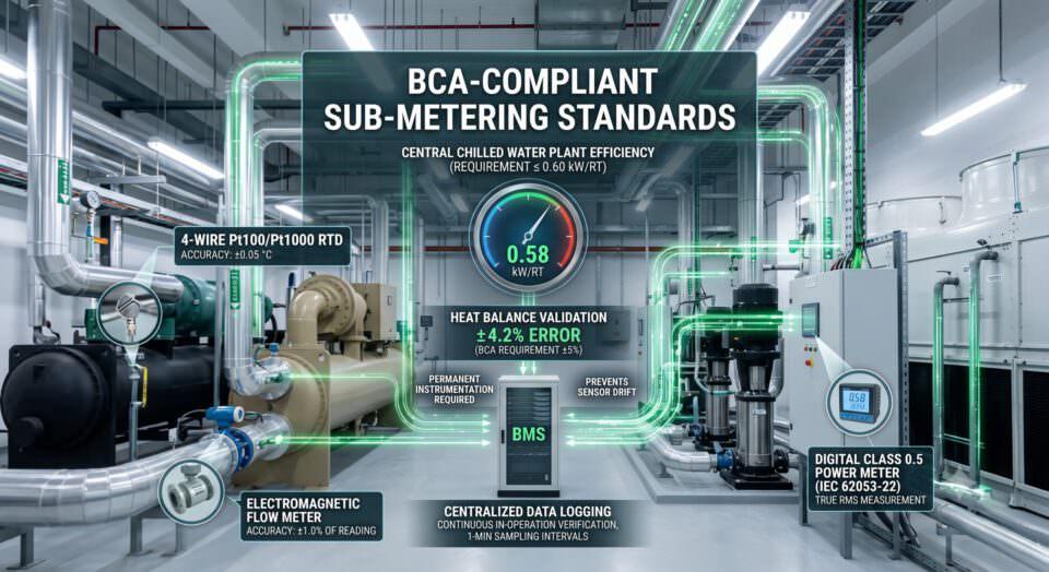
Why Un-Monitored Systems Fail In-Operation Audits
(BCA-Compliant Sub-Metering Standards)
The era of passing a Singapore Building and Construction Authority (BCA) energy audit using a one-off “snapshot” measurement or manual paper logbook is officially over. Under current BCA Green Mark frameworks and periodic energy audit standards for central cooling plants, auditors no longer accept single-point manual readings taken during a brief window of steady-state operation.
In-operation compliance demands continuous, automated data logging that proves your central chilled water plant maintains its efficiency target—typically $\le 0.60$ kW/RT for water-cooled plants—over months of dynamic building loads.
Without permanent, high-precision instrumentation linked to a robust Building Management System (BMS) or Energy Management System (EMS), even well-maintained chillers fail audits due to unverified system data, uncalibrated sensor drift, or failed heat balance checks.
The Shift to Continuous In-Operation Verification
Legacy audit models relied on third-party consultants bringing portable ultrasonic flow meters and temp gauges for a single afternoon. Today’s BCA in-operation verification model requires building operators to continuously record, compute, and archive central cooling plant metrics.
Why Manual & Non-Permanent Setup Fails:
-
Intermittent Data Gaps: Audit software flags gaps in historical operational trends. Missing data points during variable-load periods automatically invalidate verification windows.
-
Transient Load Inaccuracies: Spot checks catch a chiller at a single operating point (e.g., 80% load). They miss part-load degradation, low $\Delta T$ syndrome, and improper pump staging during off-peak hours.
-
Non-Compliant Heat Balance Validation: BCA audits require heat balance validation where total heat rejected at the condenser equals total cooling produced at the evaporator plus electrical power input within a tight error margin.
Where:
-
$Q_{\text{condenser}}$ = Heat rejected by the cooling tower circuit (kW or RT)
-
$Q_{\text{evaporator}}$ = Cooling capacity supplied to the building (kW or RT)
-
$W_{\text{electrical}}$ = Total power input to chillers, pumps, and cooling tower fans (kW)
If your facility cannot produce continuous data proving that heat balance error remains within $\pm 5\%$ for at least 80% of operating hours, your audit will be rejected outright.
Hardware Standards: BCA Precision Specifications
Passing an in-operation audit requires installing fixed instrumentation that meets strict accuracy tolerances across the entire signal pathway—from sensor to analog card to BMS software database.
+------------------+     +--------------------+     +-------------------+
|  Primary Sensor  | --> | Transmitter / I/O  | --> | Digital Data Log  |
|  (e.g., Pt100)   |     | (4-20mA / Modbus)  |     | (1-Min Sampling)  |
+------------------+     +--------------------+     +-------------------+
  (Accuracy: ±0.05°C)       (Class 0.5 Power)         (Immutable Archive)
1. Temperature Sensors & Delta T Measurement
Temperature differentials ($\Delta T$) across evaporators and condensers are often as narrow as $5.0\text{ }^\circ\text{C}$ to $6.0\text{ }^\circ\text{C}$. An error of just $0.3\text{ }^\circ\text{C}$ in return or supply temperature creates a $5\text{–}6\%$ error in calculated cooling capacity, immediately failing heat balance limits.
-
Sensor Standard: 4-wire Pt100 or Pt1000 Resistance Temperature Detectors (RTDs).
-
Calibration Tolerance: Factory-paired sensors calibrated to within $\le \pm 0.05\text{ }^\circ\text{C}$across the operating range ($0\text{ }^\circ\text{C}$ to $40\text{ }^\circ\text{C}$).
-
Installation Mandate: Sensors must be installed in thermowells filled with heat-conductive paste and positioned in pipe elbows or flowing stream zones—never in stagnant boundary layers.
2. Thermal Energy & Flow Meters
In-line flow meters are essential for calculating instantaneous tonnage ($Q = \dot{m} \cdot C_p \cdot \Delta T$). Clamp-on meters are acceptable only for temporary cross-verification, not permanent logging.
-
Primary Recommendation: Electromagnetic flow meters installed directly in full-bore chilled water and condenser water lines.
-
Accuracy Requirement: Volumetric flow accuracy within $\le \pm 1.0\%$ of actual reading across operating velocities ($0.5\text{ m/s}$ to $5.0\text{ m/s}$).
-
Upstream/Downstream Runs: Minimum of 5 pipe diameters upstream and 3 pipe diameters downstream of straight, unobstructed pipe to eliminate turbulent flow patterns.
3. Digital Power Meters
Recording power draw requires dedicated true-RMS power meters for every individual component in the plant room (chillers, chilled water pumps, condenser water pumps, and cooling tower fans).
-
Meter Standard: Digital Class 0.5 or Class 0.2 power quality meters conforming to IEC 62053-22.
-
Measurement Scope: Active power (kW), apparent power (kVA), power factor (PF), and Total Harmonic Distortion (THD).
-
Current Transformers (CTs): Dedicated Class 0.5 CTs matched to meter inputs. Sharing CTs with basic panel protection relays introduces signal distortion that fails audit checks.
Preventing “Sensor Drift”: The Silent Audit Killer
Even if a plant installs compliant instruments during a retrofit, physical sensors drift over time due to thermal cycling, electrical noise, and environmental exposure.
       Calculated Plant Efficiency vs. Actual Performance

Efficiency (kW/RT)
  0.70 |                                     / (Drifting Sensor)
  0.65 |                                 .--'  [Audit Failure Zone]
  0.60 |---------------------------.--'-------------------------- (BCA Target)
  0.55 |                      .--'
  0.50 |__________________.--'________ (True Plant Performance)
       0         3         6         9        12
                         Months in Operation
A temperature sensor drifting by just $0.1\text{ }^\circ\text{C}$ per year can make a plant operating at a true $0.58\text{ kW/RT}$ appear as if it is operating at $0.64\text{ kW/RT}$ in BMS trend logs.
Best Practices for BMS Automation Engineers:
-
Annual End-to-End Recalibration: Recalibrate all RTDs, flow transmitters, and power meters every 12 months using SAC-SINGLAS accredited calibration labs or traceable field calibrators.
-
Dual-Sensor Redundancy on Critical Headers: Install dual RTDs on main chilled water supply and return headers. Configure the BMS to throw an alarm if the delta between redundant sensors exceeds $0.1\text{ }^\circ\text{C}$.
-
Automated Heat Balance Tracking: Program your BMS to run the heat balance equation automatically on a rolling 24-hour basis. Set an alert if the error exceeds $\pm 5\%$ for more than 2 consecutive hours.
Data Logging Architecture & Sampling Rates
Collecting high-precision sensor data is useless if the logging pipeline downsamples, truncates, or overwrites key historical records.
-
Sampling Interval: Record raw values for temperature, flow, power, and computed kW/RT at intervals of 1 to 5 minutes max. Hourly averages obscure system cycling and transient pump spikes.
-
Data Integrity: Store raw, unedited sensor logs in write-once-read-many (WORM) storage or secure cloud databases. BCA auditors perform spot-audits on raw CSV/SQL database dumps to check for modified log files.
-
Calculated Fields vs. Raw Inputs: Always log individual raw parameters ($T_{\text{supply}}$, $T_{\text{return}}$, $\text{Flow}$, $\text{kW}$) alongside computed outputs ($\text{RT}$, $\text{kW/RT}$). Never record only the final calculated values, as auditors must be able to re-verify math routines independently.